 UniRemoteLab
DS3502 Digital Potentiometer with ESP32: Dim an LED over I2C
A potentiometer turned by code instead of a hand: the ESP32 sets the DS3502 wiper, reads the voltage it produces, and turns it into LED brightness. I2C, analog input and PWM in one experiment.
▶ Run it on a real boardFree as a guest for a few minutes, or with your university account
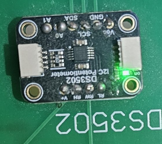
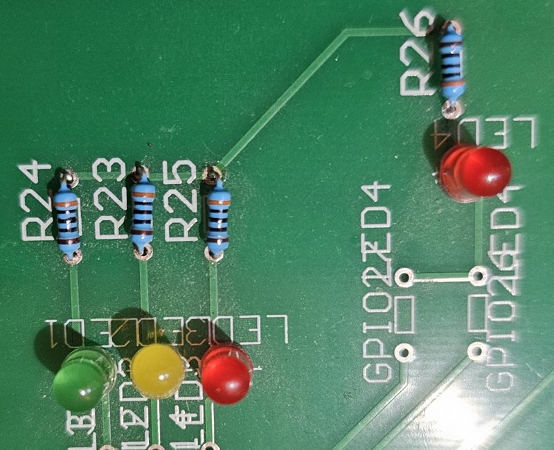
Wiring on the lab board
| Part | Pin |
|---|---|
| DS3502 over I2C | 0x28 on GPIO22 / GPIO23 |
| Wiper RW | GPIO25 |
| LED4 | GPIO26 |
Full code
// Experiment 6: LED brightness with the DS3502 digital potentiometer
// Relays: K5 and K6 (I2C), K14 (DS3502 wiper to GPIO25), K13 (LED4 from GPIO26)
// Library: Adafruit DS3502
// The DS3502 wiper only goes to GPIO25, so: set the resistance -> read the voltage -> turn it into PWM on LED4
// ⚠️ RH is tied to 5V, so we never go above 80 to keep the voltage under 3.3V
// ⚠️ GPIO25 is on ADC2: do not turn on Wi-Fi in this sketch
#include <Wire.h>
#include <Adafruit_DS3502.h>

Adafruit_DS3502 pot;
const int WIPER_PIN = 25;
const int LED_PIN = 26;     // LED4 through K13
const int MAX_SAFE = 80;
int wiper = 0;

void setup() {
  Serial.begin(115200);
  pinMode(LED_PIN, OUTPUT);
  Wire.begin(22, 23);
  if (!pot.begin(0x28, &Wire)) {
    Serial.println("DS3502 not found");
    while (true) delay(1000);
  }
  Serial.println("Send a value 0..80, or wait for the automatic sweep");
}

void loop() {
  if (Serial.available()) {
    int v = Serial.parseInt();
    while (Serial.available()) Serial.read();
    wiper = constrain(v, 0, MAX_SAFE);
  } else {
    wiper = (wiper + 5) % (MAX_SAFE + 1);   // automatic sweep
  }
  pot.setWiper(wiper);
  delay(50);
  int mv = analogReadMilliVolts(WIPER_PIN);
  int pwm = constrain(map(mv, 0, 3300, 0, 255), 0, 255);
  analogWrite(LED_PIN, pwm);
  Serial.print(wiper); Serial.print(" "); Serial.print(mv); Serial.print(" "); Serial.println(pwm);
  delay(400);
}
The libraries are already installed in the lab.
How it works
- pot.setWiper() moves the wiper to a position from 0 to 127, which changes the voltage on its RW pin.
- analogReadMilliVolts(25) reads that voltage; map() turns 0 to 3300 mV into a PWM value from 0 to 255, and analogWrite() lights the LED with it.
- If you type nothing, the code sweeps the values by itself, so the LED brightens and starts again.
Common mistakes and fixes
- The voltage always reads 0
- GPIO25 is on ADC2, which does not work while WiFi is on. Don't use WiFi in this sketch.
- Why not go above 80?
- On this board RH is tied to 5 V; above 80 the wiper would exceed the 3.3 V the ESP32 pin can take.
- DS3502 not found
- The I2C relays are open, or Wire.begin(22, 23) is missing.
 AC dimmer
 Switch and LED